Installation and user manual · CLT-1102
RGB LED Control Unit
01Overview
Receiver unit with colour management for RGB LED lines.
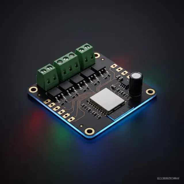
CLT-1102 RGB Led Dimmer is an industrial automation control board designed for RGB LED lighting in pergola and winter garden systems. It operates within a 12–24V DC input voltage range and supports 680W power output. It precisely controls RGB LED brightness levels and color transitions with On/Off, Cycle (color loop), and Dimmer functions. Integration with smart home systems is provided through dry contact and shutter inputs. Wireless communication module enables control via mobile app or remote control.
- Model code
- CLT-1102
- Product family
- Light Control
- Architecture
- Standalone
- Status
- Coming soon
02Safety notes
Installation must be carried out by a qualified electrician in accordance with applicable regulations.
This section is in preparation
Our team is preparing the content. If you need it now, write to us with the product code. Write to us
03In the box
This section is in preparation
Our team is preparing the content. If you need it now, write to us with the product code. Write to us
04Wiring
The terminal and pin table is already in the Technical data section.
05Mounting and installation
This section is in preparation
Our team is preparing the content. If you need it now, write to us with the product code. Write to us
06Configuration and pairing
This section is in preparation
Our team is preparing the content. If you need it now, write to us with the product code. Write to us
07Operation
This section is in preparation
Our team is preparing the content. If you need it now, write to us with the product code. Write to us
08Troubleshooting
This section is in preparation
Our team is preparing the content. If you need it now, write to us with the product code. Write to us
09Technical data
- Model code
- CLT-1102
- Product family
- Light Control
- Architecture
- Standalone
- Status
- Coming soon
- Unit
- Piece
- Datasheet
- Revision 1
Electrical characteristics
| Parameter | Value |
|---|---|
| Input Voltage | 12–24V DC |
| Maximum Power | 680W |
| LED Channels | 3 (R / G / B) |
| Dimmer Resolution | PWM (0–100% / channel) |
| Functions | On/Off + Cycle + Dimmer |
| Dry Contact | 3 channels (COM / Cycle / Cycle Stop) |
| Shutter Input | 3 channels (N / Up / Down) |
| Wireless | Wi-Fi + Bluetooth |
| Protection | Overcurrent, short circuit, thermal protection |
| Operating Temperature | −20°C ~ +60°C |
| PCB Size | 105 × 55 mm |
| Mounting | Enclosure mounting |
Connectors
Power SocketPower & RGB LED Output
| Pin | Signal | Description |
|---|---|---|
| 1 | 12–24V DC (+) | Supply voltage positive input |
| 2 | 12–24V DC (−) | Supply voltage negative (GND) |
| 3 | LED (+) | LED common anode positive power output |
| 4 | LED B | Blue channel PWM output |
| 5 | LED G | Green channel PWM output |
| 6 | LED R | Red channel PWM output |
Sensor SocketSensor & Contact Inputs
| Pin | Signal | Description |
|---|---|---|
| 7 | Dry Contact COM | Dry contact common |
| 8 | Dry Contact Cycle | Dry contact — Start Cycle mode (color loop) |
| 9 | Dry Contact Cycle Stop | Dry contact — Stop Cycle mode |
| 10 | Shutter N | Shutter neutral connection |
| 11 | Shutter Up | Shutter up command (LED on / increase brightness) |
| 12 | Shutter Down | Shutter down command (LED off / decrease brightness) |
Datasheet notes
- The board must be mounted inside an enclosure. Do not expose directly to outdoor conditions.
- Before connecting LEDs, ensure the supply voltage and polarity are correct.
- RGB LED strip must be Common Anode (+) type. Common Cathode (−) is not supported.
- Dry contact inputs must be potential-free (volt-free).
- Total LED strip length and power consumption must not exceed the board's 680W power capacity.
- Pay attention to R, G, B channel connection order. Incorrect connection causes color mixing.
10Revision history
No revision has been published yet.