Installation and user manual · CND-1102
Double Motor Control Unit
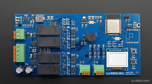
01Overview
Board driving two motors in sync, with independent operating modes.
CND-1102 Double Motor Control Unit is an industrial automation control board designed for dual DC motor drives used in pergola and awning systems. It operates within a 12–24V DC input voltage range and supports up to 10A motor current per channel. With its built-in dual Hall-Encoder input, it independently tracks the position of both motors. It features three different operating modes: Synchronous, Single (independent), and Free (manual). Real-time position and status information is displayed on the built-in OLED screen. Integration with smart home systems is provided through dry contact and shutter inputs.
- Model code
- CND-1102
- Product family
- Control Boards
- Architecture
- Standalone
- Status
- Available
02Safety notes
Installation must be carried out by a qualified electrician in accordance with applicable regulations.
This section is in preparation
Our team is preparing the content. If you need it now, write to us with the product code. Write to us
03In the box
This section is in preparation
Our team is preparing the content. If you need it now, write to us with the product code. Write to us
04Wiring
The terminal and pin table is already in the Technical data section.
05Mounting and installation
This section is in preparation
Our team is preparing the content. If you need it now, write to us with the product code. Write to us
06Configuration and pairing
This section is in preparation
Our team is preparing the content. If you need it now, write to us with the product code. Write to us
07Operation
This section is in preparation
Our team is preparing the content. If you need it now, write to us with the product code. Write to us
08Troubleshooting
This section is in preparation
Our team is preparing the content. If you need it now, write to us with the product code. Write to us
09Technical data
- Model code
- CND-1102
- Product family
- Control Boards
- Architecture
- Standalone
- Status
- Available
- Unit
- Piece
- Datasheet
- Revision 1
Electrical characteristics
| Parameter | Value |
|---|---|
| Input Voltage | 12–24V DC |
| Max. Input Current | 10A (per channel) |
| Motor Channels | 2 (independent H-Bridge) |
| Motor Output Current | 10A × 2 channels (continuous) |
| Motor Type | DC Motor (Forward / Reverse) |
| Encoder Support | Dual Hall-Effect Quadrature (A/B phase) |
| Dry Contact | 2 channels (Up / Down) + COM |
| Shutter Input | 3 channels (N / Up / Down) |
| Display | Built-in OLED — position and status indicator |
| Wireless | Wi-Fi + Bluetooth |
| Operating Modes | Synchronous / Single / Free |
| Protection | Overcurrent, short circuit, stall detection, thermal protection |
| Synchronization | Real-time position comparison and automatic alignment |
| Operating Temperature | −20°C ~ +60°C |
| PCB Size | 150 × 90 mm |
| Mounting | Enclosure mounting (DIN rail optional) |
Connectors
CN1Motor Power Outputs
| Pin | Signal | Description |
|---|---|---|
| 1 | Motor 2 Reverse | Motor 2 reverse direction power output |
| 2 | Motor 2 Forward | Motor 2 forward direction power output |
| 3 | Motor 1 Reverse | Motor 1 reverse direction power output |
| 4 | Motor 1 Forward | Motor 1 forward direction power output |
CN2Motor 1 Hall-Encoder Input
| Pin | Signal | Description |
|---|---|---|
| 5 | Encoder A | Motor 1 Hall-Encoder phase A signal |
| 6 | Encoder B | Motor 1 Hall-Encoder phase B signal |
| 7 | Encoder VCC (+3.3V) | Motor 1 Hall-Encoder positive supply |
| 8 | Encoder GND (−) | Motor 1 Hall-Encoder negative supply |
CN3Motor 2 Hall-Encoder Input
| Pin | Signal | Description |
|---|---|---|
| 9 | Encoder A | Motor 2 Hall-Encoder phase A signal |
| 10 | Encoder B | Motor 2 Hall-Encoder phase B signal |
| 11 | Encoder VCC (+3.3V) | Motor 2 Hall-Encoder positive supply |
| 12 | Encoder GND (−) | Motor 2 Hall-Encoder negative supply |
CN4Power Input
| Pin | Signal | Description |
|---|---|---|
| 13 | 12–24V DC (+) | Supply voltage positive input |
| 14 | 12–24V DC (+) | Supply voltage positive input (parallel) |
| 15 | 12–24V DC (−) | Supply voltage negative (GND) |
| 16 | 12–24V DC (−) | Supply voltage negative (GND, parallel) |
CN5Contact Inputs
| Pin | Signal | Description |
|---|---|---|
| 17 | Dry Contact COM | Dry contact common |
| 18 | Dry Contact DOWN | Dry contact — down direction |
| 19 | Dry Contact UP | Dry contact — up direction |
| 20 | Shutter Up | Shutter up command |
| 21 | Shutter Down | Shutter down command |
| 22 | Shutter N | Shutter neutral connection |
Datasheet notes
- The board must be mounted inside an enclosure. Do not expose directly to outdoor conditions.
- Before connecting motors, ensure the supply voltage and polarity are correct.
- Encoder cable length should not exceed 3 meters; use shielded cable for longer distances.
- The + and − terminals on CN4 are doubled for parallel connection. Both + terminals and both − terminals are connected to each other.
- Dry contact inputs must be potential-free (volt-free).
- Always perform connection check in Free Mode before commissioning.
- In SYNC mode, it is recommended that both motors are of the same type and same RPM specifications.
- Motors should not be operated without setting the limits.
10Revision history
No revision has been published yet.